Computer power supply units (PSU) deliver the power to the PC hardware via a number of cables with connectors. Their generic specifications for various desktop systems are defined in Intel's design guides, which are periodically revised. Their latest standard is PSU Design Guide rev.1.31 released on April 2013. This document combines the requirements for ATX12V v2.4 and its five variations. Note that some brand name manufacturers did not follow this standard.
Standard ATX power supplies typically have the main power connector P1, additional 12V connectors, as well as peripheral, floppy drive, serial ATA, and PCI Express® receptacles, which we will describe below.

For the operation basics of SMPS PSU see our power supply tutorial. The original ATX systems had 20-pin main connector P1. When PCI Express® bus was introduced, PCIe cards needed up to 75W extra. To provide the additional wattage, the old part has been replaced by a new 24-pin P1. Accordingly, differentATX-style PSU
If you want to do some testing of a stand alone unit, to start it up outside of a PC case you need to short PS_ON# line to the common. Otherwise, only 5V standby voltage will be present.
Under normal operation, PS_ON# is activated when you press and release the computer power button while it is in standby mode. Some Apple models have this signal reversed.
Also note that many brands such as Apple's Power Mac, Dell (during certain years), Compaq and HP used proprietary boards with entirely different pin designations- see this for info on some brand name power supplies.
All voltages are referenced to the same common (if you need to measure any voltage, connect the return lead of your voltmeter to any of the COM contacts).
The rated current of the main Molex connector is 6A per contact. This means with the old 20-pin style you can't get more than 18A from 3.3V and 24A from 5V. That's why in early 2000's, some motherboards with 3.3V >18A and 5V >24A (mainly dual CPU AMD systems) used an auxiliary 6-pin power cable. It was removed from ATX12V spec v2.0 in 2003 because extra wires were added to P1. For more information on form factors see our computer PSU tutorial.
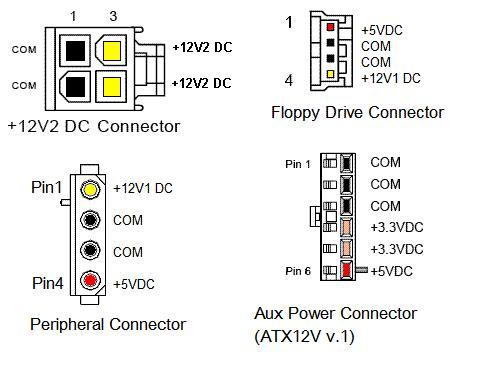
When the industry began using voltage regulation modules (VRM) running off 12V2 to energize CPU and other motherboard components, the bulk of the wattage shifted to 12 volt buss. Most of today's motherboards supply their CPU with a separate 12 volt cable, which has 4 pins for ATX style (sometimes called P4) or 8 or more pins for EPS and non-standard high-power systems. Some PSUs may have three or four 12 volt 4-pin connectors. The p/n for a standard P4 is 39-01-2040 or equivalent.
Peripheral power connector goes to disk drives, colling fans, and other smaller devices. There may also be a floppy drive cable.
Note that the wire numbers in Serial Power ATA (SATA) connector are not 1:1. There are three pins for each voltage. One pin from each voltage is used for pre-charge in the backplane. The mating serial plug of ATA devices contains both signal and power segments.
Some units may also have an optional 2x3 socket that can be used for auxiliary functions, such as fan monitoring and control, IEEE-1394 power source, and a remote sense of 3.3 V.
Power supply unit (computer)
From Wikipedia, the free encyclopedia

A power supply unit (PSU) converts mains AC to low-voltage regulated DC power for the internal components of a computer. Modern personal computers universally use a switched-mode power supply. Some power supplies have a manual selector for input voltage, while others automatically adapt to the supply voltage.
Most modern desktop personal computer power supplies conform to the ATX specification, which includes form factor and voltage tolerances. While an ATX power supply is connected to the mains supply, it always provides a 5 V standby (5VSB) voltage so that the standby functions on the computer and certain peripherals are powered. ATX power supplies are turned on and off by a signal from themotherboard. They also provide a signal to the motherboard to indicate when the DC voltages are in spec, so that the computer is able to safely power up and boot. The most recent ATX PSU standard is version 2.31 of mid-2008.
Contents
[hide]Functions[edit]


The desktop computer power supply changes alternating current from a wall socket to low-voltage direct current to operate the processor and peripheral devices. Several direct-current voltages are required, and they must be regulated with some accuracy to provide stable operation of the computer. A power supply railor voltage rail refers to a single voltage provided by a power supply unit (PSU). Although the term is generally used in electronic engineering, many people, especially computer enthusiasts, encounter it in the context of personal computer power supplies.
First-generation microcomputer and home computer power supply units used a heavy step-down transformerand a linear power supply. Modern computers use switched-mode power supplies (SMPS) with a ferrite-coredhigh frequency transformer. The switched-mode supply is much lighter and less costly, and is more efficient, than an equivalent linear power supply.
Computer power supplies may have short circuit protection, overpower (overload) protection, overvoltage protection, undervoltage protection, overcurrent protection, and over temperature protection.
Recent power supplies have a standby voltage available, to allow most of the computer system to be powered off. When the computer is powered down but the power supply is still on, it can be started remotely via Wake-on-LAN and Wake-on-ring or locally via Keyboard Power ON (KBPO) if the motherboard supports it.
This standby voltage is generated by a smaller power supply inside the unit. It originally was used to supply the voltage regulator, located on the low voltage side of the transformer allowing the regulator to measure output voltages. The regulator controls the switching transistors insulated by optocoupplers or pulse transfomers. Standby power output required to modify this part of the unit to deliver higher output current and give the regulator of the main power supply an enable signal, called PS-ON, to power up and became mechnical and electrical specified by the ATX standard. The standby power source was a small linear power supply with conventional transformer, later changed to a switching power supply, sharing some components of the main unit due costs of manufacturing and energy saving requirements.
Power supplies may have passive or active power factor correction (PFC). Passive PFC is a simple way of increasing the power factor by putting a coil in series with the primary filter capacitors. Active PFC is more complex and can achieve higher PF, up to 99%.
Development[edit]


Original IBM PC, XT and AT standard[edit]
The first IBM PC power supply unit (PSU) supplied two main voltages: +5 V and +12 V. It supplied two other voltages, −5 V and −12 V, but with limited amounts of power. Most microchips of the time operated on 5 V power. Of the 63.5 watts these PSUs could deliver, most of it was on this +5 V rail.
The +12 V supply was used primarily to operate motors such as in disk drives and cooling fans. As more peripherals were added, more power was delivered on the 12 V rail. However, since most of the power is consumed by chips, the 5 V rail still delivered most of the power. The −12 V rail was used primarily to provide the negative supply voltage to the RS-232 serial ports. A -5 V rail was provided for peripherals on the ISA bus, but was not used by the motherboard.
An additional wire referred to as Power Good is used to prevent digital circuitry operation during the initial milliseconds of power supply turn-on, where output voltages and currents are rising but not yet sufficient or stable for proper device operation. Once the output power is ready to use, the Power Good signal tells the digital circuitry that it can begin to operate.
Original IBM power supplies for the PC (model 5150), XT and AT included a line-voltage power switch that extended through the side of the computer case. In a common variant found in tower cases, the line-voltage switch was connected to the power supply with a short cable, allowing it to be mounted apart from the power supply.
An early microcomputer power supply was either fully on or off, controlled by the mechanical line-voltage switch, and energy saving low-power idle modes were not a design consideration of early computer power supplies. These power supplies were generally not capable of power saving modes such as standby or "soft off", or scheduled turn-on power controls.
Due to the always-on design, in the event of a short circuit, either a fuse would blow, or a switched-mode supply would repeatedly cut the power, wait a brief period of time, and attempt to restart. For some power supplies the repeated restarting is audible as a quiet rapid chirping or ticking emitted from the device.
ATX standard[edit]
Main article: ATX

When Intel developed the ATX standard power supply connector (published in 1995), microchips operating on 3.3 V were becoming more popular, beginning with the Intel 80486DX4 microprocessor in 1994, and the ATX standard supplies three positive rails: +3.3 V, +5 V, and +12 V. Earlier computers which wished to operate on 3.3 V typically used a simple but inefficient linear regulator to generate it from the +5 V rail.
The ATX connector provides multiple wires and power connections for the 3.3 V supply, because it is most sensitive to voltage drop in the supply connections. Another ATX addition was the +5 V SB (standby) rail for providing a small amount of standby power, even when the computer was nominally "off".

There are two basic differences between AT and ATX power supplies: the connectors that provide power to the motherboard, and the soft switch. In ATX-style systems, the front-panel power switch provides only a control signal to the power supply and does not switch the mains AC voltage. This low-voltage control allows other hardware or software to turn the system on and off.
ATX12V standard[edit]
As transistors become smaller on chips, it becomes preferable to operate them on lower supply voltages, and the lowest supply voltage is often desired by the densest chip, the central processing unit. In order to supply large amounts of low-voltage power to the Pentium and subsequent microprocessors, a special power supply, the voltage regulator module began to be included on motherboards. Newer processors require up to 100 amperes at 2 volts or less, which is impractical to deliver from off-board power supplies.
Initially, this was supplied by the main +5 V supply, but as power demands increased, the high currents required to supply sufficient power became problematic. To reduce the power losses in the 5 V supply, with the introduction of the Pentium 4 microprocessor, Intel changed the processor power supply to operate on +12 V, and added the separate four-pin P4 connector to the new ATX12V 1.0 standard to supply that power.
Modern high-powered graphics processing units do the same thing, resulting in most of the power requirement of a modern personal computer being on the +12 V rail. When high-powered GPUs were first introduced, typical ATX power supplies were "5 V-heavy", and could only supply 50–60% of their output in the form of 12 V power. Thus, GPU manufacturers, to ensure 200–250 watts of 12 V power (peak load, CPU+GPU), recommended power supplies of 500–600 W or higher. More modern ATX power supplies can deliver almost all (typically 80–90%) of their total rated capacity in the form of +12 V power.
Because of this change, it is important to consider the +12 V supply capacity, rather than the overall power capacity, when using an older ATX power supply with a more recent computer.
Low-quality power supply manufacturers sometimes take advantage of this overspecification by assigning unrealistically high power supply ratings, knowing that very few customers fully understand power supply ratings.[1]
+3.3 V and +5 V rails[edit]
These voltage supplies are rarely a limiting factor; generally any supply with a sufficient +12 V rating will have adequate capacity at lower voltages. However, a large quantity of hard drives or PCI cards will create a greater load on the +5 V rail.
Most former CPUs and most logic devices on the motherboard, also including some series of 80486, were designed to operate on 5 volts. Power supplies designed for these generations of computers control the 5 volt rail and were defined to deliver a specified tolerance depending on the load ratio of the 12 volts rail. 12 volts was used for fan motors, drive motors and serial interfaces also using the −12 volt supply. A further use was for audio amplifiers on sound cards, sometimes filtered by a 9 volt linear regulator to cut the noise of the motors.
Since some series of 80386, CPUs use lower voltages like 3.3 or 3.45 volts. Motherboard were equipped with linear voltage regulators, supplied by the 5 volts rail and configurable by jumpers or dip switches. As newer generations of CPUs required higher currents, larger heat sinks and switching mode regulators like buck converters were used.
ATX standard power supplies were required to deliver 3.3 volts. This voltage is generated by shifting and transforming the pulses of the 5 volt rail on an additional choke to an further rectifier into its separate rail and controlled by the present device.[2] With generations of computers using a Pentium 4 or similar CPU the core voltage of the CPUs became specified to various voltages, most likely below 2 volts. The required buck converters were not longer fed from the 5 volts and changed to a 12 volts input.
A small regulator is installed in some drives to keep the +3.3 V stable by feeding it from the +5 V rail.
Entry-Level Power Supply Specification[edit]
Entry-Level Power Supply Specification (EPS) is a power supply unit meant for high-power-consumption computers and entry-level servers. Developed by the Server System Infrastructure (SSI) forum, a group of companies including Intel, Dell, Hewlett-Packard and others, that works on server standards, the EPS form factor is a derivative of the ATX form factor. The latest specification is v2.93.
The EPS standard provides a more powerful and stable environment for critical server-based systems and applications. EPS power supplies have a 24-pin motherboard power connector and an eight-pin +12 V connector. The standard also specifies two additional four-pin 12 V connectors for more power-hungry boards (one required on 700–800 W PSUs, both required on 850 W+ PSUs). EPS power supplies are in principle compatible with standard ATX or ATX12V motherboards found in homes and offices but there may be mechanical issues where the 12 V connector and in the case of older boards the main connector overhang the sockets.[3] Many PSU vendors use connectors where the extra sections can be unclipped to avoid this issue. As with later versions of the ATX PSU standard there is also no -5 V rail.
| Rail | Color mark |
|---|---|
| 12V1 | Yellow (black) |
| 12V2 | Yellow |
| 12V3 | Yellow (blue) |
| 12V4 | Yellow (green) |
Multiple +12 V rails[edit]
As power supply capacity increased, the ATX power supply standard was amended (beginning with version 2.0[4]) to include:
This is a safety limit on the amount of power that may pass, in case of a fault, through any one wire. That much power can significantly overheat a wire, and would be more likely to melt the insulation and possibly start a fire. Each wire must be current-limited to no more than 20 A; typical supplies guarantee 18 A without triggering the current limit. Power supplies capable of delivering more than 18 A at 12 V connect wires in groups to two or more current sensors which will shut down the supply if excess current flows. Unlike a fuse or circuit breaker, these limits reset as soon as the overload is removed.
Ideally, there would be one current limit per wire, but that would be prohibitively expensive. Since the limit is far larger than the reasonable current draw through a single wire, manufacturers typically group several wires together and apply the current limit to the entire group. Obviously, if the group is limited to 240 VA, so is each wire in it. Typically, a power supply will guarantee at least 17 A at 12 V by having a current limit of 18.5 A, plus or minus 8%. Thus, it is guaranteed to supply at least 17 A, and guaranteed to cut off before 20 A.
These groups are the so-called "multiple power supply rails". They are not fully independent; they are all connected to a single high-current 12 V source inside the power supply, but have separate current limit circuitry. The current limit groups are documented so the user can avoid placing too many high-current loads in the same group. Originally, a power supply featuring "multiple +12 V rails" implied one able to deliver more than 20 A of +12 V power, and was seen as a good thing. However, people found the need to balance loads across many +12 V rails inconvenient. When the assignment of connectors to rails is done at manufacturing time it is not always possible to move a given load to a different rail.
Rather than add more current limit circuits, many manufacturers have chosen to ignore the requirement and increase the current limits above 20 A per rail, or provide "single-rail" power supplies that omit the current limit circuitry. (In some cases, in violation of their own advertising claims to include it.[6]) The requirement was deleted from version 2.3 (March 2007) of the ATX12V power supply specifications.[7]
Because of the above standards, almost all high-power supplies claim to implement separate rails, however this claim is often false; many omit the necessary current-limit circuitry,[8]both for cost reasons and because it is an irritation to customers.[9] (The lack is sometimes advertised as a feature under names like "rail fusion" or "current sharing".)
12 V–only supplies[edit]
Since 2011, Fujitsu and other Tier 1 manufacturers[10] have been manufacturing systems containing motherboard variants which require only a 12 V supply from a custom made PSU (typically rated at 250–300 W). DC-DC conversion, providing 5 V and 3.3 V, is done on the motherboard; the proposal is that 5 V and 12 V supply for other devices, such as HDDs, will be picked up at the motherboard rather than from the PSU itself (though this does not appear to be fully implemented as of January 2012).
The reasons given for this approach to power supply are that it eliminates cross-load problems, simplifies and reduces internal wiring which can affect airflow and cooling, reduces costs, increases power supply efficiency and reduces noise by bringing the power supply fan speed under the control of the motherboard. Other advantages it offers is the potential ability to power a PC off a sealed lead-acid 12 V battery, or from automotive power without using a power inverter.[citation needed]
At least two of Dell's business PCs introduced in 2013, the Optiplex 9020 and Precision T1700, ship with 12 V–only power supplies and implement 5 V and 3.3 V conversion exclusively on the motherboard.
Power rating[edit]
The overall power draw on a PSU is limited by the fact that all of the supply rails come through one transformer and any of its primary side circuitry, like switching components. Total power requirements for a personal computer may range from 250 watts to more than 1000 watts for a high-performance computer with multiple graphics cards. Personal computers usually require 300 to 500 watts.[9] Power supplies are designed around 40% greater than the calculated system power consumption. This protects against system performance degradation, and against power supply overloading. Power supplies label their total power output, and label how this is determined by the amperage limits for each of the voltages supplied. Some power supplies have no-overload protection.
The system power consumption is a sum of the power ratings for all of the components of the computer system that draw on the power supply. For certain graphics cards, the PSU's 12 V rating is crucial. If the total 12 V rating on the power supply is higher than the suggested rating of the card, then that power supply may fully serve the card if any other 12 V system components are taken into account. The manufacturers of these computer system components, especially graphics cards, tend to over-rate their power requirements, to minimize support issues due to too low of a power supply.[citation needed]
Although a power supply with a larger than needed power rating will have an extra margin of safety against overloading, such a unit is often less efficient and wastes more electricity at lower loads than a more appropriately sized unit. For example, a 900-watt power supply with the 80 Plus Silver efficiency rating (which means that such a power supply is designed to be at least 85-percent efficient for loads above 180 W) may only be 73% efficient when the load is lower than 100 W, which is a typical idle power for a desktop computer. Thus, for a 100 W load, losses for this supply would be 37 W; if the same power supply was put under a 450 W load, for which the supply's efficiency peaks at 89%, the loss would be only 56 W despite supplying 4.5 times the useful power.[11][12] For a comparison, a 500-watt power supply carrying the 80 Plus Bronze efficiency rating (which means that such a power supply is designed to be at least 82-percent efficient for loads above 100 W) may provide an 84-percent efficiency for a 100 W load, wasting only 19 W.[13]
A power supply that is self-certified by its manufacturer will claim output ratings that may be double or more than what is actually provided.[14][15] To further complicate this possibility, when there are two rails that share power through down-regulating, it also happens that either the 12 V rail or the 5 V rail overloads at well below the total rating of the power supply. Many power supplies create their 3.3 V output by down-regulating their 5 V rail, or create 5 V output by down-regulating their 12 V rails. The two rails involved are labeled on the power supply with a combined amperage limit. For example the 5 V and 3.3 V rails are rated with a combined total amperage limit. For a description of the potential problem, a 3.3 V rail may have a 10 A rating by itself (33 W), and the 5 V rail may have a 20 A rating (100 W) by itself, but the two together may only be able to output 110 W. In this case, loading the 3.3 V rail to maximum (33 W), would leave the 5 V rail only be able to output 77 W.
Efficiency[edit]
See also: Green computing
A test in 2005 revealed computer power supplies are generally about 70–80% efficient.[16] For a 75% efficient power supply to produce 75 W of DC output it would require 100 W of AC input and dissipate the remaining 25 W in heat. Higher-quality power supplies can be over 80% efficient; energy efficient PSU's waste less energy in heat, and requires less airflow to cool, and as a result will be quieter.
As of 2012 some high-end consumer PSUs can exceed 90% efficiency at optimal load levels, though will fall to 87-89% efficiency during heavy or light loads. Google's server power supplies are more than 90% efficient.[17] HP's server power supplies have reached 94% efficiency.[18] Standard PSUs sold for server workstations have around 90% efficiency, as of 2010.
The energy efficiency of a power supply drops significantly at low loads. Therefore it is important to match the capacity of a power supply to the power needs of the computer. Efficiency generally peaks at about 50–75% load. The curve varies from model to model (examples of how this curve looks can be seen on test reports of energy efficient models found on the 80 PLUS website).
Various initiatives are underway to improve the efficiency of computer power supplies. Climate savers computing initiative promotes energy saving and reduction of greenhouse gas emissions by encouraging development and use of more efficient power supplies. 80 PLUS certifies power supplies that meet certain efficiency criteria, and encourages their use via financial incentives. Efficient power supplies also save money by wasting less power; as a result they use less electricity to power the same computer, and they emit less waste heat which results significant energy savings on central air conditioning in the summer. The gains of using an efficient power supply are more substantial in computers that use a lot of power.
Appearance[edit]

Most desktop personal computer power supplies are a square metal box, and have a large bundle of wires emerging from one end. Opposite the wire bundle is the back face of the power supply, with an air vent and an IEC 60320 C14 connector to supply AC power. There may be a power switch or a voltage selector switch or both.
A label on one side of the box lists technical information about the power supply, including safety certifications and maximum output power. Common certification marks for safety are the UL mark, GS mark, TÜV, NEMKO, SEMKO, DEMKO, FIMKO, CCC, CSA, VDE, GOST R mark and BSMI. Common certificate marks for EMI/RFI are the CE mark, FCC and C-tick. The CE mark is required for power supplies sold in Europe and India. A RoHS or 80 PLUS can also sometimes be seen.
Dimensions of an ATX power supply are 150 mm width, 86 mm height, and typically 140 mm depth, although the depth can vary from brand to brand.
Some power supplies come with sleeved cables, which besides being more aesthetically pleasing, also make wiring easier and have a less detrimental effect on airflow.
Connectors[edit]
Typically, power supplies have the following connectors (all are Molex (USA) Inc Mini-Fit Jr, unless otherwise indicated):
- PC Main power connector (usually called P1): This is the connector that goes to the motherboard to provide it with power. The connector has 20 or 24 pins. One of the pins belongs to the PS-ON wire (it is usually green). This connector is the largest of all the connectors. In older AT power supplies, this connector was split in two: P8 and P9. A power supply with a 24-pin connector can be used on a motherboard with a 20-pin connector. In cases where the motherboard has a 24-pin connector, some power supplies come with two connectors (one with 20-pin and other with 4-pin) which can be used together to form the 24-pin connector.
- 12V only power connector (labelled P1, though it is not compatible with the ATX 20 or 24 pin connector): This is a 16-pin Molex connector supplying the motherboard with six 12 V lines with common returns, a 'supply OK' signal, a 'PSU ON' signal and an 11 V auxiliary supply. One pin is left unused.[19]
- 12V only System monitoring (P10): This is a 171822-8 AMP or equivalent connector carrying a supply to the PSU fan and sense returns.[19]
- ATX12V 4-pin power connector (also called the P4 power connector). A second connector that goes to the motherboard (in addition to the main 24-pin connector) to supply dedicated power for the processor. For high-end motherboards and processors, more power is required, therefore EPS12V has an 8-pin connector.

- 4-pin Peripheral power connectors: These are the other, smaller connectors that go to the various disk drives of the computer. Most of them have four wires: two black, one red, and one yellow. Unlike the standard mains electrical wire color-coding, each black wire is a ground, the red wire is +5 V, and the yellow wire is +12 V. In some cases these are also used to provide additional power to PCI cards such as FireWire 800cards.
- 4-pin Molex (Japan) Ltd power connectors (usually called Mini-connector, mini-Molex, or Berg connector): This is one of the smallest connectors that supplies a 3.5-inch floppy drive with power. In some cases, it can be used as an auxiliary connector for AGP video cards. Its cable configuration is similar to the Peripheral connector.
- Auxiliary power connectors: There are several types of auxiliary connectors designed to provide additional power if it is needed.
- Serial ATA power connectors: a 15-pin connector for components which use SATA power plugs. This connector supplies power at three different voltages: +3.3, +5, and +12 volts.
- 6-pin Most modern computer power supplies include 6-pin connectors which are generally used for PCI Express graphics cards, but a newly introduced eight-pin connector should be seen on the latest model power supplies. Each PCI Express 6-pin connector can output a maximum of 75 W.
- 6+2 pin For the purpose of backwards compatibility, some connectors designed for use with high end PCI Express graphics cards feature this kind of pin configuration. It allows either a 6-pin card or an 8-pin card to be connected by using two separate connection modules wired into the same sheath: one with 6 pins and another with 2 pins. Each PCI Express 8-pin connector can output a maximum of 150 W.
- An IEC 60320 C14 connector with an appropriate C13 cord is used to attach the power supply to the local power grid.
Modular power supplies[edit]

A modular power supply provides a detachable cable system, offering the ability to remove unused connections at the expense of a small amount of extra electrical resistance introduced by the additional connector.[20] This reduces clutter, removes the risk of dangling cables interfering with other components, and can improve case airflow. Many modular supplies have some permanent multi-wire cables with connectors at the ends, such as PC main and 4-pin Molex, though newer supplies marketed as "Fully Modular" allow even these to be disconnected.
Other form factors[edit]
The Thin Form Factor with a 12 V connector (TFX12V) configuration has been optimized for small and low profile microATX and FlexATX system layouts. The long narrow profile of the power supply fits easily into low profile systems. The fan placement can be used to efficiently exhaust air from the processor and core area of the motherboard, making possible smaller, more efficient systems using common industry components.[21]
Most portable computers have power supplies that provide 25 to 200 watts. In portable computers (such as laptops) there is usually an external power supply (sometimes referred to as a "power brick" due to its similarity, in size, shape and weight, to a real brick) which converts AC power to one DC voltage (most commonly 19 V), and further DC-DC conversion occurs within the laptop to supply the various DC voltages required by the other components of the portable computer.
Some web servers use a single-voltage 12 volt power supply. All other voltages are generated by voltage regulator modules on the motherboard.[17]


Life span[edit]
Life span is usually specified in mean time between failures (MTBF), where higher MTBF ratings indicate longer device life and better reliability. Using higher quality electrical components at less than their maximum ratings or providing better cooling can contribute to a higher MTBF rating because lower stress and lower operating temperatures decrease component failure rates.[22]
An estimated MTBF value of 100,000 hours (roughly, 140 months) at 25 °C and under full load is fairly common.[23] Such a rating expects that, under the described conditions, 77% of the PSUs will be operating failure-free over three years (36 months); equivalently, 23% of the units are expected to fail within three years of operation. For the same example, only 37% of the units (fewer than a half) are expected to last 100,000 hours without failing.[a] The formula for calculating predicted reliability, R(t), is
- R(t) = e − ttMTBF
where t is the time of operation in the same time units as the MTBF specification, e is 2.71828, and tMTBF is the MTBF value as specified by a manufacturer.[24][25]
Power supplies for servers, industrial control equipment, or other places where reliability is important may be hot swappable, and may incorporate N+1 redundancy; if N power supplies are required to meet the load requirement, one extra is installed to provide redundancy and allow for a faulty power supply to be replaced without downtimes.[26]
Wiring diagrams[edit]


|
| ||||||||||||||||||||||||||||||||||||||||||||||||||||||||||||||||||||||||||||||||||||||||||||||||||||||||||||||||||||||||||||||||
Testing[edit]
Thanks to :
wiki and